How to wire a joystick with Arduino?

Integrating a joystick with an Arduino opens up a range of exciting project possibilities, from interactive games to innovative control systems. The HW-504 joystick module is an excellent choice for such projects due to its straightforward functionality and ease of integration. This guide will walk you through the process of wiring the HW-504 joystick datasheet to an Arduino and provide a basic code example to get you started.
Materials Needed
- Arduino Board (e.g., Arduino Uno, Nano, etc.)
- HW-504 Joystick Module
- Breadboard and Jumper Wires
- Optional: Resistors for specific configurations
Understanding the HW-504 Joystick Module
The HW-504 joystick module is equipped with several pins:
- VCC: Power supply pin (typically 5V)
- GND: Ground pin
- VRx: Analog output for the X-axis (horizontal movement)
- VRy: Analog output for the Y-axis (vertical movement)
- SW: Push-button switch (if available)
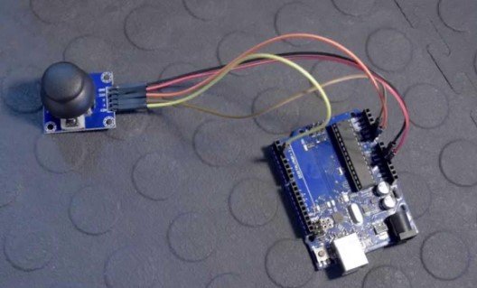
Wiring the Joystick to Arduino
1. Connect Power and Ground
- VCC (Joystick) → 5V (Arduino): Connect the VCC pin of the joystick to the 5V pin on the Arduino.
- GND (Joystick) → GND (Arduino): Connect the GND pin of the joystick to one of the GND pins on the Arduino.
2. Connect Analog Outputs
- VRx (Joystick) → A0 (Arduino): Connect the VRx pin (X-axis output) to the A0 analog input pin on the Arduino.
- VRy (Joystick) → A1 (Arduino): Connect the VRy pin (Y-axis output) to the A1 analog input pin on the Arduino.
3. Connect the Push-button (Optional)
- SW (Joystick) → Digital Pin (e.g., D2) (Arduino): Connect the SW pin (if available) to a digital pin on the Arduino, such as pin D2.
Read also: The Role of Technology in Modern Real Estate Transactions
Writing the Arduino Code
Here’s a basic code example to read the joystick values and print them to the Serial Monitor, including the push-button state if your joystick has one:
cpp
Copy code
// Define joystick pins
const int joystickX = A0;
const int joystickY = A1;
const int joystickButton = 2; // Change if using a different pin
void setup() {
// Initialize serial communication
Serial.begin(9600);
// Set joystick button pin as input
pinMode(joystickButton, INPUT_PULLUP); // Use INPUT_PULLUP to enable internal pull-up resistor
}
void loop() {
// Read the joystick values
int xValue = analogRead(joystickX);
int yValue = analogRead(joystickY);
// Read the button state
int buttonState = digitalRead(joystickButton);
// Print joystick values to the Serial Monitor
Serial.print(“X: “);
Serial.print(xValue);
Serial.print(” | Y: “);
Serial.print(yValue);
// Print button state to the Serial Monitor
Serial.print(” | Button: “);
if (buttonState == LOW) {
Serial.println(“Pressed”);
} else {
Serial.println(“Released”);
}
// Delay before next reading
delay(100);
}
Testing and Calibration
- Upload the Code: Connect your Arduino to your computer, upload the code, and open the Serial Monitor (set to 9600 baud).
- Move the Joystick: Observe changes in X and Y values as you move the joystick. Values should range from 0 to 1023.
- Press the Button: Test the button by pressing and releasing to see changes in the button state.
Troubleshooting
- Check Connections: Ensure all connections are secure and properly aligned.
- Verify Pin Definitions: Confirm that the pin definitions in your code match your physical wiring.
- Test Power Supply: Ensure the joystick is receiving adequate power from the Arduino.
Conclusion
Integrating the HW-504 joystick with an Arduino is a straightforward process that adds interactivity to your projects. By following this guide, you can effectively read joystick movements and button presses, laying the foundation for innovative and engaging applications. For more details on the HW-504 joystick module, visit the Besomi Product Page.


